


One of the consistently re-occurring problems in architecture is how to cover a large space, when you available materials are shorter then the gap you wish to cover. A Simple bridge can merely be a plank across a gap, But what if the planks you have are shorter then the Gap.
Another example is that of a roof. Placing a plank across two posts gives you a simple roof. If you lean two shorter planks together on top of the posts, you can cover a distance longer then a single piece. The slope has some advantages – it will shed snow and rain, but has a big disadvantage structurally. The two sloped planks will tend to push the tops of the posts outwards.
There are a couple of solutions to this problem. Firstly, it can be countered by replacing your posts with a battered wall. A battered wall is one where the wall that is wider at the bottom then the top. This was common when dealing with masonry and other compressive materials.
The second option is to tie the bottoms of the 2 leaning members together. This tie can be rope, or a chain, or several smaller members joined together – since it will be resisting the outward push of the roof, and therefore only be in Tension, it can be quite slender.
This 3 member system, with 2 leaning planks and a rope to tie them together at the bottom forms a simple truss, and when used, it will only push down (And not out) on the posts holding it up, so it is refereed to as a Closed System.
Combining multiple triangles will give you a larger truss. The First known wooden truss bridge was built by the Romans and is Depicted on the Trajan Column in Rome – It was built in 102A.D over the Danube River. (Below)

So why do trusses work. Besides being made up of triangles, which are non deformable shapes, a truss allows for greater beam depth. The deeper a beam is, the more load it can carry over a given span. That is why a floor in your house framed with 2×8 lumber has less bounce then a floor framed with 2×6 lumber. The other demonstration of this is to bend a metal ruler. When Flat, it is quite flexible, however when placed on edge, it is rigid.
The other thing to know about beams, is that the loaded side is in compression, and the unloaded side is in tension. This means there is an area in the middle, where the bean is experiencing neither a tensile or compressive load. This area is known as the Neutral Axis,and we can remove material from the Neutral axis, since it doesn’t do any work. It simply needs to hold the working ends apart.
If you look at a truss, you will see various patterns of tension and compressive members (remember, those under tension will be smaller) often you will see that the alignment of these members reverses at the midpoint of the truss. this is to counteract shear forces.
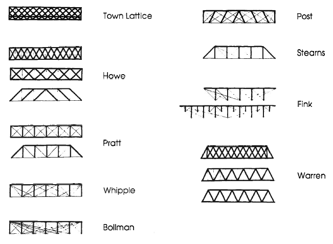
Truss design was quite active in the mid 19th century. New Materials (Iron and Steel) made larger trusses possible, and large trusses were needed by railways to span large North American rivers in rugged terrain, and for spanning large train sheds and Armories.
